

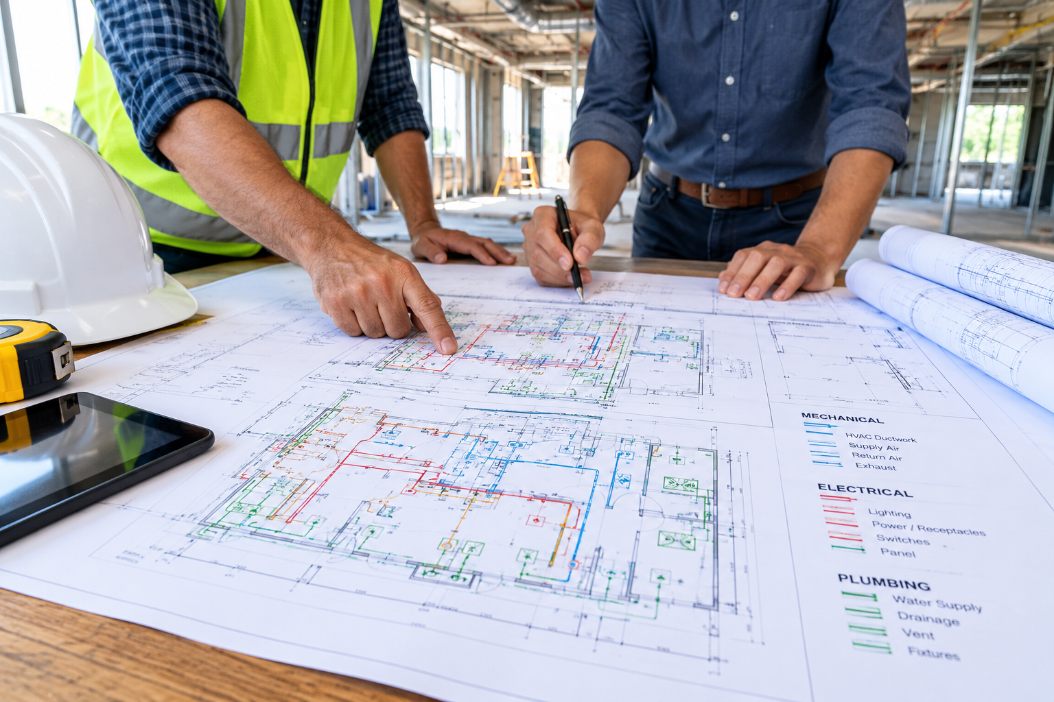

A construction project involves much more than walls, windows, and a roof. Behind every comfortable room, working light, and reliable water supply is a network of systems that must fit together correctly. When these systems are poorly planned, contractors may face unexpected expenses, installation conflicts, inspection problems, and frustrating delays.
This is where MEP drawings become essential. MEP stands for mechanical, electrical, and plumbing, three building systems that work together to make a property functional, safe, and comfortable. These drawings help contractors, engineers, architects, and other project participants understand how equipment, wiring, ventilation, pipes, and fixtures should be installed.
For Florida property owners and contractors, understanding MEP documentation before construction begins can make project planning more organized. Whether you are building a new home, renovating a commercial space, or expanding an existing property, knowing what these drawings include can help you make better decisions before work starts.
1. What Are MEP Drawings, and Why Do They Matter?
MEP drawings are technical plans that show the layout, specifications, and coordination of a building's mechanical, electrical, and plumbing systems. They complement architectural and structural drawings by explaining how essential building services will be installed within the proposed design.
Architectural plans show the arrangement of rooms, doors, windows, and other building features. Structural drawings address the components that support the building. MEP drawings focus on the systems that provide heating, cooling, lighting, electricity, water, drainage, and ventilation.
These systems cannot be designed independently without considering their relationship to the rest of the building. A ventilation duct may need to pass through a ceiling space that also contains electrical conduits and plumbing lines. Without coordination, these components can compete for the same space.
Well-prepared drawings help identify potential conflicts before materials are purchased or installation begins. They also provide a shared reference for contractors and the professionals responsible for reviewing the project.
For example, a restaurant renovation may require new kitchen equipment, additional electrical capacity, revised plumbing connections, and updated ventilation. Coordinating these requirements early can help prevent expensive changes once construction is underway.
2. Mechanical Drawings: Heating, Cooling, and Ventilation
Mechanical drawings primarily address heating, ventilation, and air conditioning (HVAC) systems. They may show equipment locations, ductwork routes, supply and return air outlets, ventilation requirements, thermostats, and other components relevant to the design.
In Florida, mechanical planning deserves particular attention because of the state's hot weather, humidity, and extended cooling season. An HVAC system must be appropriate for the building's design and intended use, not simply large enough to cool the space.
A properly coordinated mechanical design considers factors such as building size, room layout, occupancy, insulation, ventilation needs, and equipment performance. The precise calculations and documentation required depend on the project and applicable codes.
Consider a homeowner adding a bedroom to an existing house. The new room may affect the existing HVAC system's capacity and airflow. If these issues are overlooked, the addition could experience uneven temperatures or inadequate ventilation.
Mechanical drawings also help contractors understand where ducts, equipment, and controls belong. They can reveal potential conflicts with beams, ceilings, lighting fixtures, and plumbing lines before installation begins.
Reviewing mechanical plans early helps the project team coordinate equipment requirements, confirm available space, and identify questions that need to be resolved before work starts.
3. Electrical Drawings: Power, Lighting, and Safety
Electrical drawings explain how electricity will be distributed throughout a building. Depending on the project, they may include lighting layouts, receptacle locations, switching arrangements, panel schedules, circuit information, equipment connections, and other electrical details.
These plans help electricians understand how the building's electrical systems are intended to function. They also allow the design team to coordinate outlets, lighting, and equipment with the architectural layout and the needs of future occupants.
For example, a commercial office renovation may introduce additional computers, printers, meeting-room displays, and specialized equipment. If the electrical requirements are not evaluated during planning, the project may need circuit changes or additional work after construction begins.
Electrical coordination is also important when equipment requires dedicated power or when lighting locations must align with ceiling layouts. A lighting fixture installed where ductwork or a structural component is planned can create avoidable rework.
Electrical drawings should be prepared and reviewed by appropriately qualified professionals, with required calculations, specifications, and certifications provided where applicable. Contractors should verify that the submitted plans reflect the actual project scope and equipment requirements.
Before installation, compare electrical layouts with architectural and mechanical drawings. This simple coordination step can help identify conflicting locations and clarify installation responsibilities.
4. Plumbing Drawings: Water Supply, Drainage, and Fixtures
Plumbing drawings show how water enters a building, reaches fixtures, and leaves through drainage and waste systems. Depending on the project, they may also address vent piping, water heaters, sanitary connections, storm drainage, and specialized plumbing equipment.
These plans are important because plumbing routes must work within the building's physical layout. Pipe sizes, slopes, connection points, fixture locations, and available space all influence the final installation.
Imagine a property owner converting a garage into a bathroom and laundry area. The new fixtures need appropriate water supply and drainage connections. If the proposed layout does not account for existing pipes, elevations, or connection requirements, the project may require additional excavation, rerouting, or design revisions.
Commercial properties can present even more complex plumbing needs. Restaurants, medical offices, and other specialized facilities may require plumbing arrangements that differ considerably from those of a standard residence.
In Florida, plumbing designs must address applicable building and plumbing code requirements, as well as relevant local utility or permitting conditions. Requirements depend on the type of work and the property's circumstances.
Contractors should review plumbing plans alongside structural and architectural documents to identify potential conflicts with foundations, beams, cabinetry, and other building components. Resolving these issues before installation can reduce disruption and help keep the work aligned with the approved design.
5. How MEP Permit Drawings in Florida Support Approvals
MEP documentation is not only an installation guide. For projects that require these plans, it can also form an important part of the building permit application.
The required documents depend on the project's size, occupancy, scope, location, and applicable exemptions. A small residential project may have different requirements from a new commercial building or a substantial renovation.
MEP permit drawings in Florida may need to demonstrate that the proposed mechanical, electrical, and plumbing systems satisfy applicable code provisions. Depending on the work, the submission may include equipment schedules, system layouts, calculations, specifications, and signed or sealed documents prepared by qualified professionals.
An application can encounter delays when required drawings are missing, system layouts conflict, equipment information is incomplete, or reviewer comments are not adequately addressed. Submitting coordinated documents that reflect the same project scope helps reduce these avoidable problems.
Before applying, confirm the current requirements with the local building department. Check whether separate trade permits or additional approvals are necessary, and verify which documents must be prepared or certified by licensed professionals.
Professional Florida MEP drawing services can help property owners and contractors organize the technical drawings needed for their projects. The appropriate service depends on the scope of work, available building information, and the requirements of the reviewing authority.
Remember that complete drawings support the review process but do not guarantee approval or a specific review timeline.
6. How to Review MEP Drawings Before Construction Begins
Even when the necessary drawings have been prepared, the project team should review them together before installation starts. This helps identify inconsistencies while changes are still relatively easy to coordinate.
Begin by confirming that the drawings reflect the latest architectural and structural plans. Check that equipment locations, fixture layouts, service routes, and other important details agree across the documents.
Next, identify potential installation conflicts. Look for ducts crossing structural members, pipes interfering with electrical equipment, and fixtures competing for limited ceiling or wall space. Confirm that equipment access and maintenance clearances are addressed where required.
Contractors should also verify that specified equipment matches the project's needs and that relevant site conditions have been considered. Existing buildings may contain hidden utilities or outdated systems that require investigation before finalizing the installation approach.
Finally, establish a clear process for handling changes. If a system needs to be relocated or an equipment specification changes, the affected drawings should be reviewed and updated by the responsible professionals before the change is implemented where required.
Keep the current drawing set accessible to everyone involved in the project. Clear document control helps prevent teams from working from outdated plans and reduces confusion during construction.
Final Thoughts
MEP drawings play a critical role in turning a building design into a functional property. Mechanical plans address heating, cooling, and ventilation; electrical plans coordinate power and lighting; and plumbing plans organize water supply and drainage.
When these systems are planned together, contractors can identify conflicts earlier, coordinate installations more effectively, and prepare more complete permit submissions.
For Florida construction projects, the best approach is to review the applicable requirements early, coordinate MEP documentation with architectural and structural plans, and resolve technical questions before work begins. Well-prepared drawings cannot eliminate every construction challenge, but they can provide a clearer path from planning and permitting to installation and final inspection.
